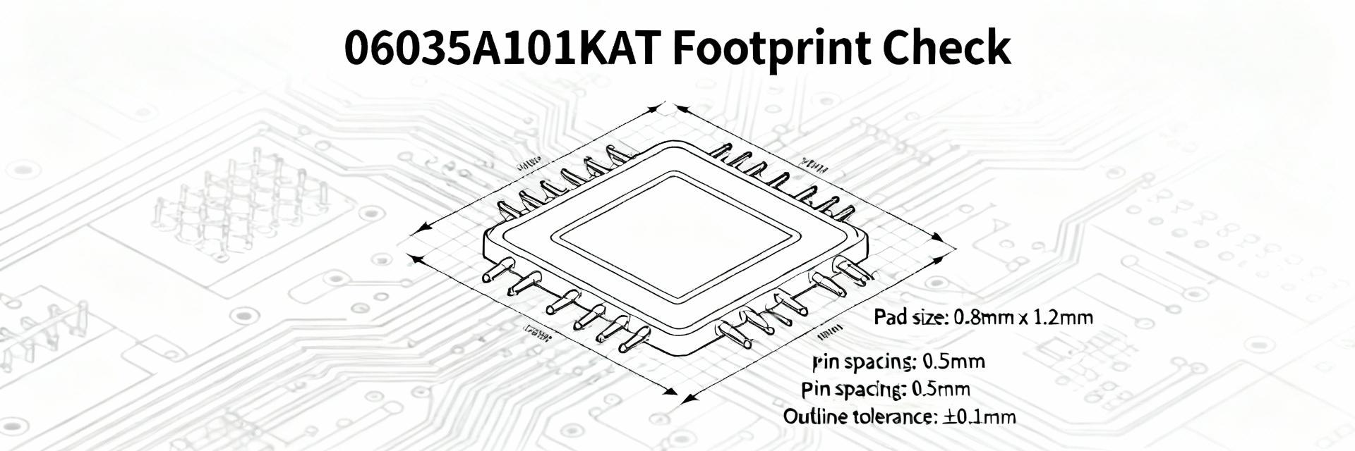
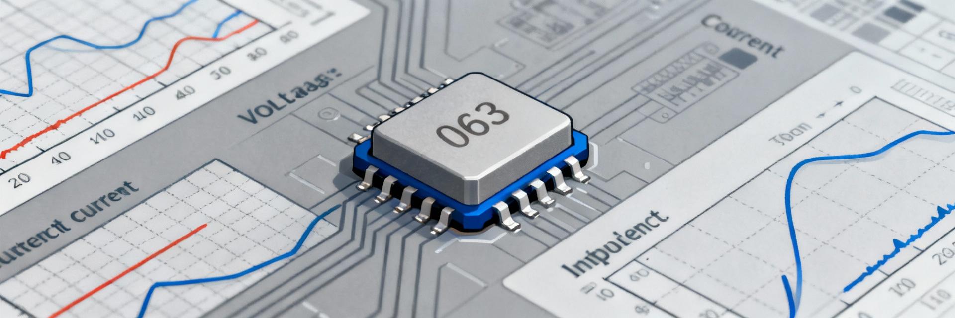
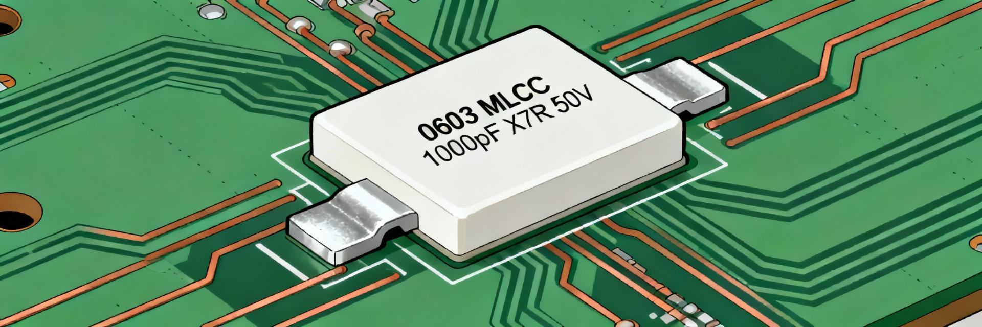
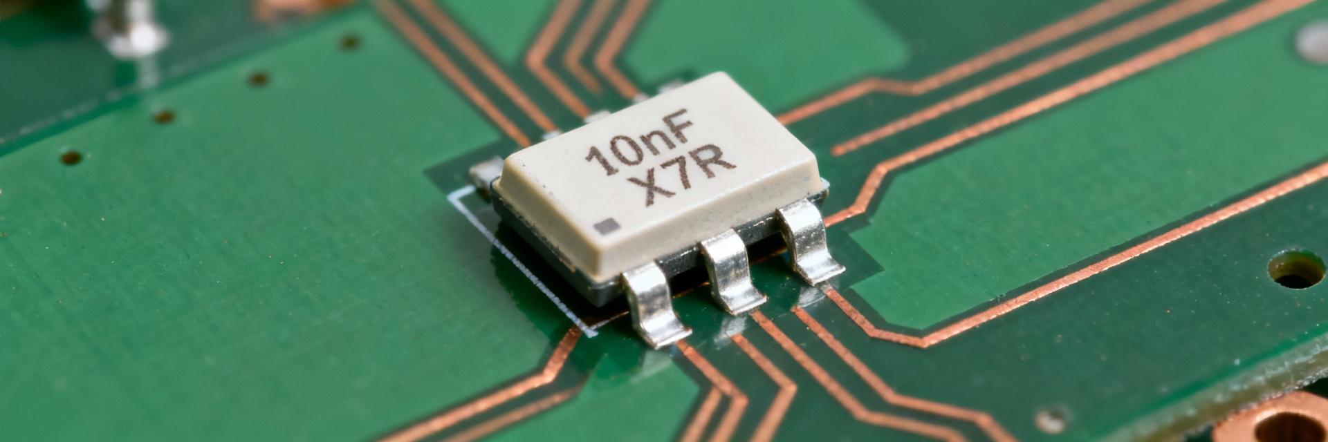
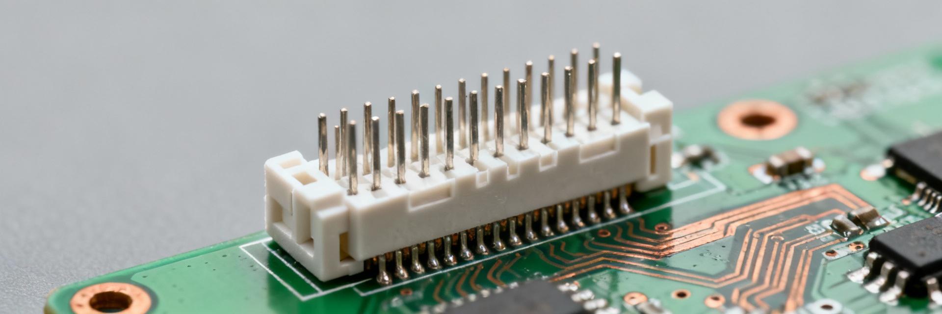
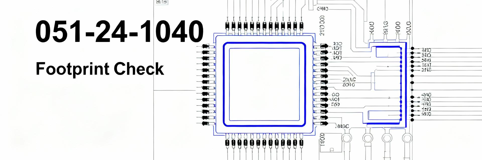
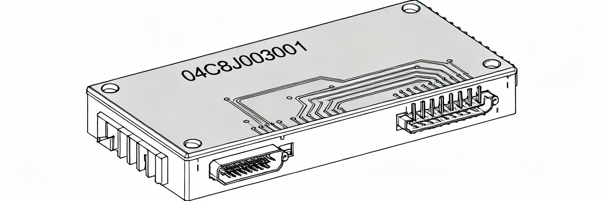
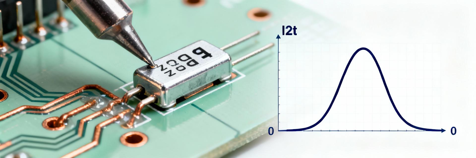
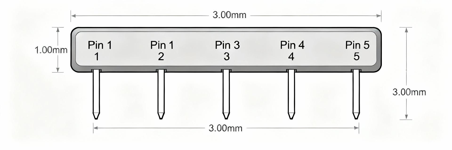
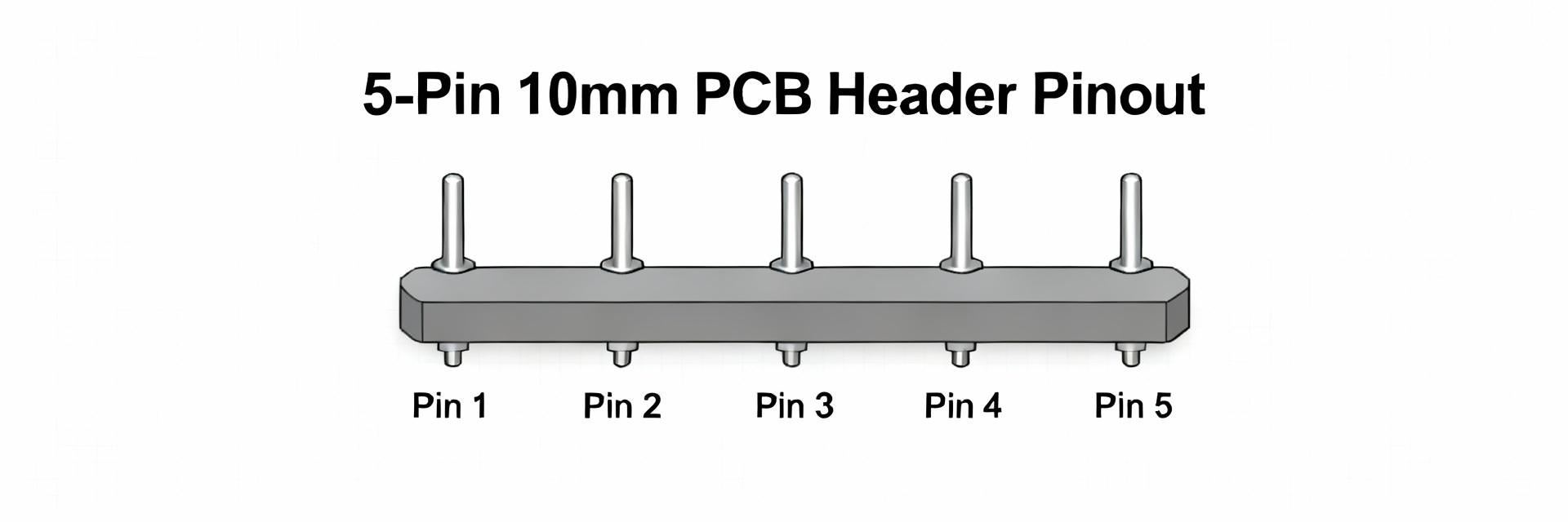
The 0428192213 connector is a 2-position, 10.00 mm (0.394") pitch power header specified in manufacturer datasheets as a high-current PCB power interconnect. Key numeric highlights engineers surface early in design reviews include: 2 positions, 10.00 mm pitch, typical datasheet current rating near 50 A per contact, common insulation materials (glass-filled nylon) and platings (tin or gold over nickel), and UL94 V-0 flammability for many variants. Designers consult these specs at schematic and thermal budgeting stages to confirm PCB copper, derating and mechanical fixing requirements. Datasheet-sourced numbers should always be rechecked against the latest manufacturer datasheet and the specific part revision before production. This article summarizes typical specs, interpretation of current rating, mechanical footprints, installation guidance, testing recommendations and practical checklists that reflect field experience and common lab verification practices. What is the 0428192213 connector? (Background introduction) What this part number identifies Point: The part number identifies a power header class connector, intended for wire-to-board or board-to-board power distribution. Evidence: Datasheets list it as a 2-position header with a 10.00 mm (0.394") centerline and through-hole mounting. Explanation: In plain language, it is a compact, two-pin power header used where moderate to high DC currents are required; common package options include vertical and right-angle THT variants and the part number encodes family, position count and configuration. Typical use cases and industry contexts Point: This connector is widely used where rugged, high-current PCB connections are needed. Evidence: Application notes and datasheets show deployments in power rails, battery distribution, industrial control and test equipment. Explanation: Typical load profiles motivating selection include 30–50 A DC rails, intermittent high-current charging pulses, and short duty cycles; selection drivers are primarily current capacity, mechanical anchoring, and reliable PCB solder joints under thermal stress. Key electrical specs & current rating (Data analysis) Rated current and how to interpret it Point: The nominal current rating listed on datasheets (commonly ~50 A per contact) reflects controlled test conditions, not guaranteed continuous field performance. Evidence: Manufacturer ratings assume specified ambient, defined copper area and thermal rise limits. Explanation: Engineers must derate for higher ambient temperatures, limited PCB copper, and single-pin loading; a practical rule is to reduce the datasheet rating by 20–40% for conservative continuous operation unless validated by thermal testing. Parameter Datasheet value (typical) Recommended operational Rated current ~50 A per contact (test conditions) 30–40 A continuous (single pin, limited copper) Test ambient ~25°C Consider derating above 40°C Cycles Specified mate/unmate cycles Validate per application Current comparison Datasheet (~50 A) 50 A Recommended (30–40 A) 30–40 A Voltage, contact resistance, and insulation characteristics Point: Voltage rating, contact resistance and insulation values determine heating and safety margins. Evidence: Typical datasheets specify a rated working voltage range, contact resistance in single-digit milliohms and insulation resistance in megaohms, plus a dielectric withstanding voltage. Explanation: Low contact resistance (mΩ) reduces I²R heating at high currents; insulation resistance and dielectric strength set creepage/clearance and system voltage limits. Measure contact resistance with four-wire methods under expected clamp forces for accurate thermal modeling. Mechanical & environmental specs (Data analysis) Dimensions, mounting and footprint essentials Point: Proper PCB footprint and mechanical anchoring are essential to reliability. Evidence: Standard dimensions include 10.00 mm pitch, typical header height variants and through-hole pin diameters sized for 1.57 mm PCBs. Explanation: Verify pad-to-pad spacing, recommended drill sizes and keepout for solder fillets; confirm board thickness and plating to ensure robust mechanical retention and sufficient solder fillet to conduct heat away from the contact. Materials, plating, temperature and flammability Point: Material choices affect corrosion resistance, wear and temperature handling. Evidence: Common insulating materials are glass-filled nylon or PA variants, contact bases are copper alloys/brass, with tin or gold over nickel platings and operating ranges that support typical industrial environments. Explanation: UL94 V-0 rated insulators limit flammability risk; choose gold plating for low contact resistance and fretting-prone applications, tin for cost-sensitive but less wear-critical uses, and confirm max operating temperature against nearby power components. Installation, mating & compatibility (Method guide) Mating components and mechanical fit Point: Mechanical fit and latch geometry determine reliable mating and retention. Evidence: Datasheets specify mating gender, recommended housings and insertion/removal forces. Explanation: Verify mating connector gender (header vs. receptacle), confirm latch or board-lock features, and perform tolerance stack-up checks for pin alignment; measure insertion force and confirm it is within ergonomic and reliability targets for your assembly and service cycles. PCB assembly and soldering recommendations Point: Correct solder process and anchoring prevent joint fatigue and warpage. Evidence: Through-hole THT is the common mounting style with recommended solder fillet profiles and wave-solder compatibility notes. Explanation: Use wave soldering or selective solder with appropriate preheat; for hand-soldering, follow controlled thermal ramp to avoid deforming the insulator and verify solder fillets visually. Provide soldermask relief where needed and include thermal reliefs only when they do not compromise heat dissipation for high-current paths. Testing, reliability & common failure modes (Case display) Recommended tests before deployment Point: A focused test matrix validates electrical and mechanical performance. Evidence: Essential tests include contact resistance (four-wire), high-current thermal soak, vibration/shock, humidity/thermal cycling and mate/unmate cycles. Explanation: Define pass/fail criteria such as ΔR Common failure modes and mitigation Point: Typical failures arise from overheating, corrosion, and solder fatigue. Evidence: Field reports and lab failure analysis commonly show contact wear, fretting corrosion, and solder joint cracks due to insufficient copper or mechanical flex. Explanation: Mitigations include increasing PCB copper pour and vias for heat spread, using redundant pins or parallel contacts for lower per-pin current, selecting appropriate plating for corrosion resistance, and designing strain reliefs to protect solder joints. Practical action checklist for engineers (Action suggestion) Pre-selection checklist Point: A short pre-selection workflow streamlines part choice. Evidence: Best-practice design reviews include current confirmation, mating part ID, footprint check, thermal budget and sample ordering. Explanation: Confirm required continuous and peak current per contact, verify mating connector IDs and footprint tolerances, check operating temperature and flammability requirements, plan derating margins and order engineering samples for thermal and mechanical validation before production release. Field & maintenance checklist Point: Simple in-field checks catch developing faults early. Evidence: Periodic inspections, contact resistance spot checks and visual plating assessment are effective. Explanation: Recommend inspection intervals based on duty cycle (e.g., quarterly for heavy-use systems), measure in-situ contact resistance with portable four-wire meters, replace connectors showing visible plating wear or ΔR above threshold (for example, a rise exceeding 10% of baseline), and keep spare connectors on hand for critical systems. Summary The 0428192213 connector is a two-position, 10.00 mm-pitch power header with a typical datasheet current rating near 50 A per contact; confirm exact specs against the latest datasheet before final selection and layout. Key design drivers are derating for ambient and PCB copper, contact resistance control to limit heating, and mechanical anchoring to prevent solder fatigue under vibration. Validation requires high-current thermal testing, four‑wire contact resistance measurement, and mate/unmate cycle testing; implement PCB copper pours and redundant contacts where necessary for reliability. FAQ What is the recommended continuous current for a 0428192213 connector in a compact PCB layout? For compact PCB layouts with limited copper, treat the datasheet ~50 A rating as a peak/test value and plan conservatively: 30–40 A continuous per contact is a practical target unless validated by thermal testing that includes PCB copper area, vias and expected ambient. Always verify with a thermal soak test under expected duty cycle. How should engineers test the contact resistance for the 0428192213 connector? Measure contact resistance using a four-wire (Kelvin) method with controlled contact force and temperature; record baseline resistance, then remeasure after thermal cycling and mate/unmate durability tests. Define a pass threshold such as ΔR less than a specified milliohm increase after N cycles to reflect acceptable degradation. When is gold plating recommended versus tin for this connector? Choose gold plating when low contact resistance, resistance to fretting corrosion, and reliable low-cycle mate/unmate performance are priorities; select tin plating for cost-sensitive, low-cycle assemblies where fretting risk is low. Consider environmental exposure and expected service life when selecting plating and confirm compatibility with solder processes. Final actionable recommendation: before production, validate the 0428192213 connector under your exact thermal, copper area and duty-cycle conditions using the manufacturer datasheet as the baseline and in-house high-current thermal testing to confirm the chosen operational current and mechanical mounting approach. i Tip: Click the blue icon to trigger a subtle SVG interaction — small, unobtrusive H5 animation added for visual affordance.
2026-01-20 12:38:06