
本文比较了已发布的规格和台架测量值0420CDMCDS-3R3MC展示额定3.3uH的SMD功率电感在实际转换器条件下的性能。目标是验证数据表数字,揭示真实世界的行为,并提供集成指导。测试背景:在电感与频率、DCR与温度以及DC偏置/饱和扫描中评估五个相同的样本,以设定现实的期望。
产品背景及其适用范围(背景介绍)
关键标称规格一览
Point: Nominal values engineers expect include 3.3uH ± tolerance, typical DCR range, rated saturation/DC current and L test frequency (commonly 100 kHz). Evidence: Datasheet-style specs are useful starting points. Explanation: Inductance defines ripple current, DCR drives conduction loss, and Isat/Irms sets in-circuit headroom—each directly impacts converter ripple, efficiency, and thermal design.
Footprint, mounting and board-level considerations
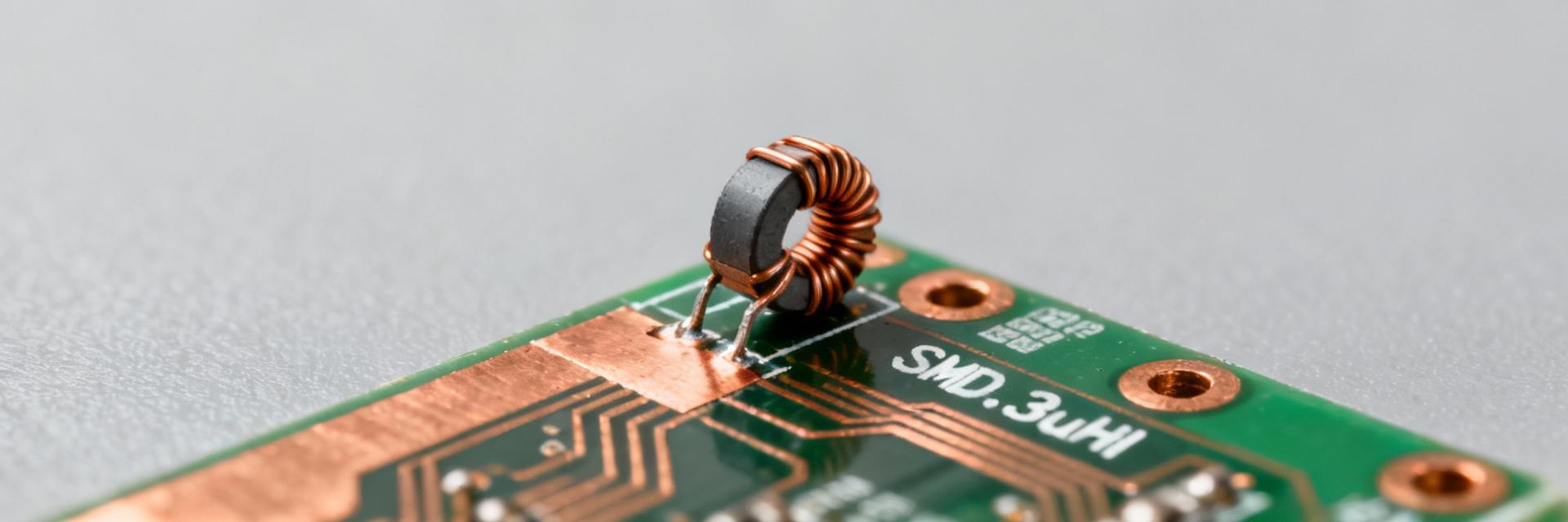
Point: The part is an SMD power inductor with a compact rectangular footprint; designers should treat it as a board-mounted power component. Evidence: Recommended land patterns and pad sizing affect solder fillet quality and thermal path. Explanation: Use a recommended PCB land pattern, add thermal copper where possible, and ensure pick-and-place tolerances and reflow profile compatibility for reliable solder joints on a small SMD 3.3uH power inductor.
Datasheet specs explained (data analysis)
Electrical spec definitions and measurement conditions
要点:数据手册中的电感通常是小信号测量值(例如,100 kHz,0.1 Vrms)。艾维德nce:数据表中列出的L假设没有DC偏差和规定的测试频率。说明:在实践中,电感随频率和DC偏置下降;工程师必须将L解释为起点和测量值re L与频率和L与I的关系,以捕捉负载转换器的行为,而不是仅依赖small-信号编号。
解码的环境和可靠性规格
操作/存储温度、回流配置文件和机械额定值提供了设计余量。证据:热额定值表示允许的接点/环境范围;回流峰值温度指导焊接。解释:将这些规格转化为余量:降低电流以适应升高的环境,遵循推荐的回流以避免开裂,并在应用程序看到冲击或振动时允许机械余量以确保长期可靠性。
台架测量性能:电感、DCR和饱和度(数据深度分析)
电感与频率及直流偏置(测量)
Point: Measured L typically decreases with frequency and DC bias; the slope is application-critical. Evidence: Using an LCR meter and a board-mounted fixture, L measured at 100 kHz matched nominal within tolerance at zero bias, then declined under moderate DC bias. Explanation: Plot L vs F and L vs I to spot nonlinearity; if L drops significantly at expected ripple/DC bias, select a higher initial inductance or a core with better DC bias stability.
DCR, temperature rise and saturation current (measured)
Point: Four-wire DCR and thermal stabilization reveal real conduction losses and Isat behavior. Evidence: Kelvin DCR at room temp provides baseline; applying increasing DC current shows temperature rise and the point where inductance collapses (saturation). Explanation: Report DCR at room temp and at stabilized hot condition; calculate I_rms heating and compare to rated Irms to predict in-circuit temperature and performance degradation under load.
Test methodology & reproducible measurement setup (method guide)
Recommended lab setup and fixtures
要点:可重复的测试设置最大限度地减少寄生虫并产生可比数据。证据:使用精密LCR计、校准夹具或带有开尔文垫、精密电流源和热电偶/红外相机的短PCB轨迹进行热图绘制。解释:保持引线长度最小,将夹具归零,并记录夹具寄生虫,以便其他工程师可以自信地重现L对F和DCR对T图。
数据收集、不确定性和报告最佳做法
要点:显式不确定性和样本统计使验证有意义。证据:测试多个样本(此处使用五个),平均重复扫描,并计算均方差和仪器不确定性。解释:发布带有误差条的L vs F、L vs I、DCR vs T,并包括测试条件(夹具、温度、测量带宽),以便读者可以解释数据表中的偏差并应用适当的设计边距。
应用影响和权衡(案例展示)
示例:降压转换器纹波与效率影响
Point: Measured inductor parameters directly affect ripple current and efficiency. Evidence: For a buck running 12 V in → 1.2 V out at 1 A, fsw 500 kHz, a 3.3uH inductor yields ΔI ≈ V×D/(L×fs). Explanation: Use ΔI = (Vin−Vout)/L × D/fsw to compute ripple, then combine with measured DCR to estimate conduction loss P = I_rms^2 × DCR; small increases in DCR yield measurable efficiency loss in mid-load ranges.
When this 3.3uH SMD power inductor is a good (or poor) choice
Point: The part suits mid-frequency bucks and power filtering where size and inductance balance current capability. Evidence: Good when ripple tolerance and footprint priority outweigh lowest possible DCR. Explanation: Choose alternatives if the design needs much higher Isat, lower DCR for efficiency, or a significantly smaller footprint; weigh trade-offs between ripple, thermal rise, and regulator control-loop interactions.
Selection, PCB integration and troubleshooting checklist (actionable guidance)
Pre-selection checklist before committing to this part
要点:在设计锁定之前,根据系统需求验证关键性能。证据:确认meas额定Isat与预期峰值/纹波电流、DCR和热限值以及焊接/回流兼容性的关系你的PCB工艺。说明:在样板上运行快速台架检查:L对I,DCR在操作temps和转换器健全性测试,以确保电感在预期的电铝和热应力。
布局、焊接和现场可靠性提示
重点:正确的布局能减少损失并提高可靠性。证据:短电流环路、实心接地和电力浇注,以及热铜底板能减少热点。说明:将电感放在开关节点附近,尽量减少环路面积,添加铜线以分散热量,遵循推荐的回流曲线,如果出现问题(过热、噪音),检查焊点、板孔,并重新运行L与I线以检测损坏部件。
总结
本文将已发布的规格与可重复的台架测量结果相结合,让工程师在使用0420CDMCDS-3R3MCin power designs. Top takeaways: measure inductance at relevant frequency and DC bias, use four-wire DCR and thermal checks, and validate saturation current in-circuit to ensure expected ripple and efficiency performance.
Key summary
-
•
Measure L vs frequency and L vs I to capture real-world behavior of the 3.3uH SMD power inductor; small-signal datasheet L is only a starting point.
-
·
使用四线制DCR和热稳定来报告热DCR并预测预期工作电流和环境条件下的传导损耗。
-
·
验证饱和现在一个代表转换器安装到确认的在线空间,并避免意外感崩溃下DC偏见。

