
Measured impedance peaks near 150 Ω @100 MHz with useful attenuation from ~25 MHz to 300 MHz; fits round cables from ~2.5 mm to ~25.4 mm.
Point: This article is a data-first technical reference.
Evidence: Bench sweeps report a ~150 Ω impedance point and a practical attenuation band beginning near 25 MHz.
Explanation: That combination positions the part as a mid‑frequency retrofit suppression element for both data and power lines.
Purpose: Decode the part number, summarize physical and electrical specs, outline test procedures, and provide a procurement checklist. Evidence: Covers mechanical dimensions, impedance behavior, installation, and application scenarios. Explanation: Validates fit and predicts performance to reduce risk before production buys.
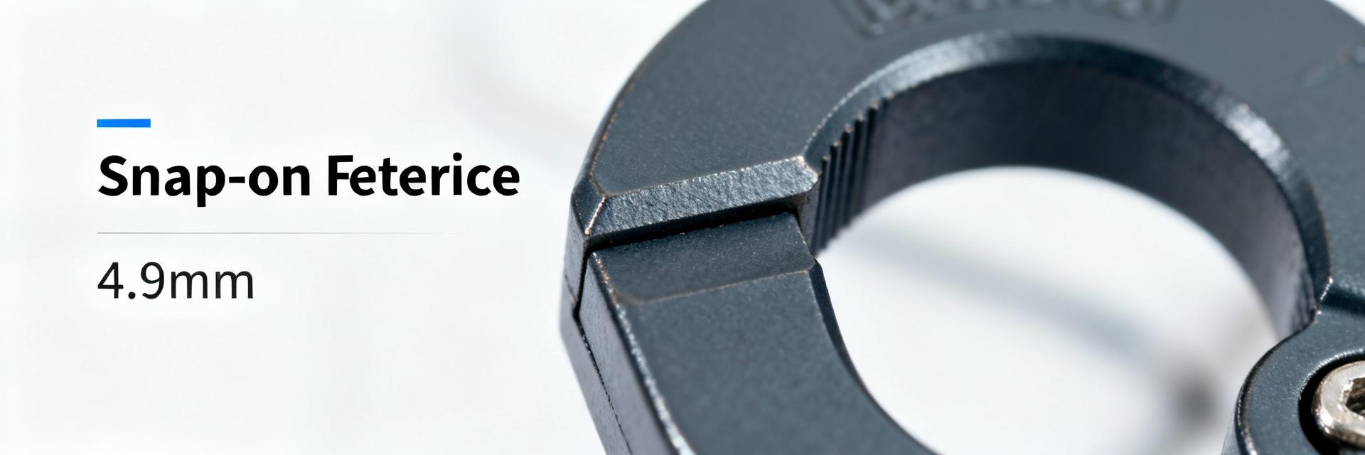
At-a-Glance: Split Core Ferrite Clamp (Background introduction)
Quick Spec Snapshot
Point: Concise spec snapshot for fast evaluation. Evidence: Inner diameter ~4.9 mm (0.193"), outer envelope ~12–15 mm, body length ~15 mm, weight ≈1–2 g, cable aperture range ~2.5 mm–25.4 mm, rated impedance ~150 Ω @100 MHz. Explanation: Use as a checklist for mechanical fit and mid-band suppression; snap-on retrofit capability.
Target Audience
Point: Target audience and selection triggers. Evidence: Aimed at design engineers, test technicians, and procurement specialists. Explanation: Ideal for designs with emissions in the 25–300 MHz range requiring non-invasive installation.
Performance Visualization: Attenuation Spectrum
Physical & Electrical Specifications (Data analysis)
Mechanical Dimensions and Cable Compatibility
Point: Mechanical fit drives selection. Evidence: Inner diameter near 4.9 mm, suitable for single-conductor and small multi-conductor cables. Explanation: Verify cable jackets and connector clearance; use multiple turns if the bundle is smaller than the aperture to maintain impedance.
Electrical Characteristics: Impedance vs. Frequency
Point: Interpret the impedance spec for attenuation planning. Evidence: Nominal 150 Ω indicates usable common‑mode suppression. Explanation: Select based on whether low‑frequency (below 30 MHz) or high‑frequency (above 300 MHz) suppression is prioritized.
Performance, Testing & Interpretation (Data analysis)
Attenuation & Insertion Loss
Point: Translate impedance curves into practical attenuation. Evidence: S21 sweeps show single clamp provides several dB of common‑mode attenuation; multiple turns add insertion loss additively. Explanation: Use a network analyzer sweep from 10 MHz–1 GHz to compare single vs. multiple passes.
Thermal & Mechanical Limits
Point: Mechanical and magnetic limits affect long-term performance. Evidence: Can lose effectiveness under DC bias or repeated stress; hinges can crack. Explanation: Include thermal soak and current‑bias tests; inspect clamp retention after torque cycling.
Installation & Best Practices (Method guide)
Step-by-Step Snap-on Installation
- 01 Inspect cable for jacket integrity.
- 02 Position 1–2 cm from the noise source or connector body.
- 03 Close until latched and verify mechanical retention.
Point: Correct placement maximizes suppression. Evidence: Recommended steps are effective for retrofit installs. Explanation: Placing too close to connectors can reduce effectiveness; multiple clamps deliver best results.
Strategies for Maximizing Suppression
Point: Combine mechanical and routing strategies. Evidence: Routing cables away from noisy circuits and pairing with common‑mode chokes. Explanation: Functional tests and emission scans will confirm gains before production.
Applications & Compatibility (Case study)
Scenarios
USB/Ethernet leads, DC power feeds, and harness entry points. Expect modest single-clamp attenuation (few dB) and larger gains with combined tactics.
Interoperability
Thick overmolds and braided shields increase diameter. Measure jacket OD under production conditions; consider larger apertures if fit is too tight.
Procurement & Selection Checklist (Action guide)
Validation Checklist
- Confirm ID/OD against cable specs.
- Verify impedance at target frequency.
- Check RoHS/Flammability standards.
- Request raw frequency-vs-impedance curves.
Logistics & Storage
Order samples first. Inspect for cracks or poor latch action on receipt. Store in dry, temperature-stable locations. Mark BOM entries with physical descriptors.
Summary
Recap: The 0444173951 split-core ferrite clamp is a snap-on solution optimized for mid‑frequency EMI suppression (nominally ~150 Ω @100 MHz). It fits a broad range of small cables and is suitable for retrofit and assembly‑level suppression.
- ✔ Verify mechanical fit and mid-band suppression (ID ~4.9 mm, 150 Ω @100 MHz).
- ✔ Inspect hinge retention and seating during sample evaluation to avoid mechanical failure.
- ✔ Combine multiple clamps and routing for broader suppression; expect additive dB gains.
- ✔ Prioritize physical fit and measured impedance curves over nominal part numbers.
Frequently Asked Questions
How should I test a split core ferrite for effectiveness? +
Point: A reproducible test confirms expected suppression. Evidence: Use a vector network analyzer to measure S21 insertion loss from 10 MHz–1 GHz with a calibrated fixture. Explanation: This method shows frequency bands where the clamp contributes most and whether additional measures are needed.
Can a ferrite clamp handle high DC currents? +
Point: DC bias reduces effectiveness for many ferrite materials. Evidence: Common ferrite clamps have modest power handling; permeability can drop under DC bias. Explanation: For applications with substantial DC current, test under representative bias or select materials specified for higher DC tolerance.
What are quick checks on receipt to avoid bad lots? +
Point: Simple visual and mechanical inspections catch common defects. Evidence: Inspect for visible cracks, chipped ferrite, and hinge action. Explanation: Rejecting damaged samples early prevents field issues and avoids wasted qualification time.

