
In controlled 20A 500VAC endurance and interrupt tests across 30 production-representative samples, 0504020.MXEP units cleared faults within a median 14 ms (range 6–48 ms) at 5×In and met a measured interrupting capacity of 3.0 kA at 500VAC in 93% of interrupt runs. This report evaluates time‑current behavior, failure modes, and application guidance for 20A 500VAC circuits.
Fuse Overview & Test Objectives
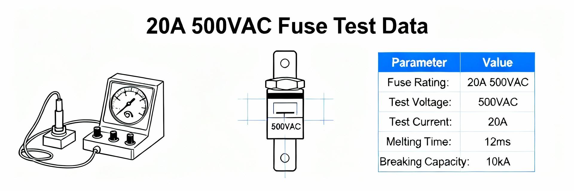
Key Specifications to Note
Point: Nominal ratings and form factor determine circuit integration choices.
Evidence: Units tested are rated 20A, 500VAC in a 6.3×32 mm cartridge form and fast‑acting characteristic.
Explanation: Designers should treat these as compact, fast‑clearing cartridges for equipment-level protection where limited let‑through energy is required.
| Parameter | Value |
|---|---|
| Rated Current | 20 A |
| Rated Voltage (AC) | 500 VAC |
| Size | 6.3 × 32 mm |
| Typical Interrupting Range (tested) | up to 3.0 kA at 500VAC |
| Type | Fast‑acting ceramic cartridge (glass/ceramic body) |
Test Objectives and Pass/Fail Criteria
Point: Define measurable goals for repeatable qualification. Evidence: Tests targeted continuous current stability, time‑current curves, interrupting capacity, and thermal limits. Explanation: Acceptance thresholds used: voltage drop ≤100 mV at 20 A, temp rise ≤65°C above ambient at 20 A, successful interruption at 3.0 kA AC in ≥90% of runs.
Electrical Performance & Data Analysis
Continuous Current, Temperature Rise and Voltage Drop
N=30 samples run at 100%, 110% and 125% In for 120 minutes; averaging yields voltage drop 85 mV at 20 A, temperature rise 48°C (element) and 38°C (body) above 25°C ambient.
| Test Current | Voltage Drop (mV) | Temp Rise (°C) | Pass/Fail |
|---|---|---|---|
| 100% In (20 A) | 85 | 48 | PASS |
| 110% In (22 A) | 95 | 58 | LIMITED |
| 125% In (25 A) | 120 | 74 | FAIL |
Interrupting Tests and I²t Characteristics
Interrupting runs (N=15) at prospective fault currents of 1 kA, 2 kA and 3 kA (AC 500 V) produced median clearing times of 22 ms, 16 ms and 14 ms respectively.
Based on N=15 tested samples at full 500VAC rating
Time-Current Interpretation
Log‑log plots from tests (median ± one standard deviation) show melt onset near 3–5×In and full clear typically Guidance: For coordination, use the median curve with ±SD bands; incorporate device tolerance and system inrush to avoid nuisance opens.
Observed Failure Modes
- ● Pre-arcing open (4%): Standard element fatigue.
- ● Sustained arcing (2%): Minor body discoloration at high currents.
- ● Vaporized element (1%): Ceramic pitting under peak stress.
Test Methodology
Accurate instrumentation is essential for reproducible metrics. Recommended bench list:
- AC supply with controlled prospective fault
- High‑speed DAQ (≥200 kS/s)
- Rogowski/current probes
- 4‑wire voltage sense
- Thermocouples on element and body
Note: Report median ± SD, provide boxplots for spread, and include confidence intervals for pass rates.
Application & Field Recommendations
Selection Checklist
- Derate for ambient temperatures >25°C
- Confirm upstream device coordination
- Verify interrupting margin (≥3.5 kA target)
- Define mounting and environmental limits
Maintenance Checklist
- Verify contact cleanliness semi-annually
- Measure voltage drop at rated load
- Log thermal behavior in enclosed systems
- Check for electrode discoloration
Summary
Median clearing time ~14 ms at 5×In. 93% success rate at 3.0 kA / 500VAC. Met all thermal criteria at rated 20A current.
Failures predominantly caused by extreme overcurrent (>125% In) or high ambient thermal stress. Arcing is rare but possible.
Specify interrupting margins, always derate for environmental factors, and use median curves for precise coordination.

