
Evidence: Manufacturer datasheets and independent catalogs consistently highlight DC-bias capacitance loss, temperature dependence, and mechanical vulnerabilities as primary concerns for small-package X7R parts.
Explanation: This article summarizes benchmark metrics, common failure modes, a repeatable test plan, and actionable QC/procurement checklists so teams can evaluate parts such as 06035C271K4Z2A with repeatable data and clear acceptance criteria.
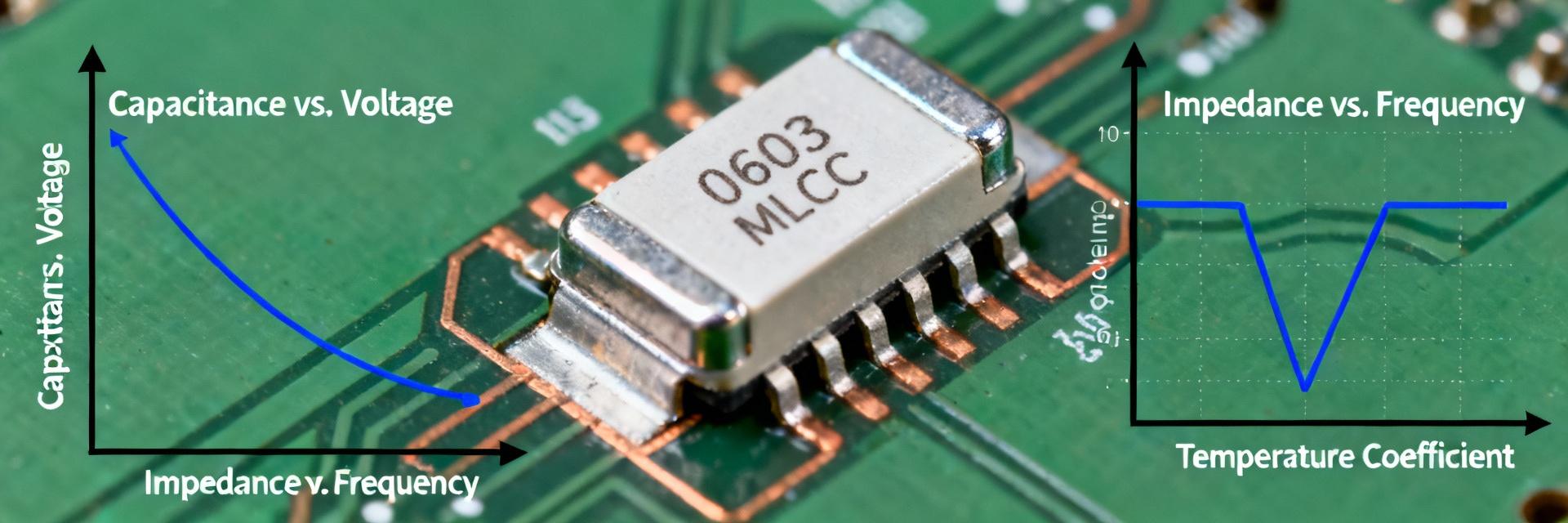
Background: Why choose a 0603 270pF X7R?
Key electrical & mechanical specs to watch
Evidence: Typical spec checklists show C_nominal 270 pF, tolerances ±1%–±10%, common voltage ratings 16–50 V, X7R temperature class rated for −55°C to +125°C, and aging behavior noted in vendor literature.
Explanation: Designers must monitor aging (ppm/month), DC-bias shift and permitted operating voltage; a short spec table below provides a concise checklist for incoming-inspection review.
| Field | Standard Specification / Example |
|---|---|
| C_nominal | 270 pF |
| Tolerance | ±5% / ±10% |
| Voltage | 16 V / 25 V / 50 V |
| Temp range | −55°C to +125°C |
| Aging rate | ~0.5–1.5% per decade |
Typical applications and design constraints
Evidence: Field reports and bench data indicate DC-bias capacitance loss of 10–35% at 5–10 V and elevated susceptibility to assembly-induced cracks in thin boards.
Explanation: Where capacitance stability under bias is critical (precision timing, narrowband RF), X7R may be unsuitable; the team should select alternative dielectrics or larger packages to meet stability requirements.
Lab benchmark summary: electrical performance metrics to report
Recommended metrics and how to present them
Evidence: Accepted benchmarks include initial capacitance (C0), percent change vs DC bias (0V, 1V, 5V, 10V), C vs temperature across −55°C to +125°C, dissipation factor (DF) or ESR, insulation/leakage current, aging rate, and Q vs frequency.
Explanation: Visuals should include C vs DC-bias curves, C vs temperature curves, and histograms of initial C spread; summary tables must report mean ± SD and 95% confidence intervals for transparency.
Test setup & sampling notes (repeatable, reproducible)
Evidence: Recommended practice uses calibrated LCR meters at specified test frequencies (e.g., 1 MHz for small caps), controlled temperature chambers, defined solder reflow profiles, and pre-bake for moisture-sensitive parts.
Explanation: Specify sample sizes (minimum 30 pcs per lot for basic characterization), report mean ± SD, and retain raw data to compute 95% CIs and enable later forensic review.
Reliability & failure-rate analysis: lab stress vs field returns
Common failure modes and root causes
- Ceramic cracking: From assembly/board flex.
- Electrode delamination: Manufacturing defect.
- Capacitance drift: Under DC bias or temperature aging.
- Insulation breakdown: Increased leakage current.
- Microfractures: Resulting from thermal cycling.
Explanation: Each mode has diagnostic signatures—sudden drop in C indicates cracking, progressive leakage rise signals insulation breakdown—and points to assembly stresses, inadequate derating or poor PCB mechanical design.
How to quantify failure rates: FIT, MTBF and confidence bounds
Evidence: FIT (failures per 10^9 device-hours) and MTBF calculations depend on observed failures, total test hours, and acceleration models such as Arrhenius (temperature) or Coffin–Manson (thermal cycling).
Explanation: Report failures per million device-hours with 90% confidence intervals, state acceleration factors and test conditions, and avoid over-extrapolation from tiny sample sizes; recommend stating sample size and censoring rules explicitly.
Step-by-step test plan to benchmark 0603 270pF X7R
Phase 1: Sample selection, board-level assembly and preconditioning
Point: Lot-level sampling and realistic assembly simulation are essential to expose assembly-sensitive failures.
Evidence: Use lot sampling rules (e.g., 30–100 pcs per lot), apply representative reflow profiles, and simulate board flex or multiple reflow cycles.
Explanation: Retain samples post-test for failure analysis and require suppliers to provide process flow documentation to correlate assembly steps with observed failures.
Phase 2: Core electrical and mechanical tests (procedures & criteria)
Point: Prioritize tests that reveal DC-bias sensitivity and mechanical robustness.
Evidence: Core tests include initial electrical (C/DF/IR), DC-bias sweep, temperature cycling (−55°C↔+125°C), thermal shock, high-temperature biased life, and board flex.
Explanation: Suggested pass/fail thresholds: capacitance shift within tolerance ±10% of C0, leakage below specified µA/V threshold, and no cracking visible under X10 inspection.
Design & mitigation strategies to lower failure risk
Design rules and derating best practices
Evidence: Practical rules include voltage derating (use higher VR or larger package), select larger case sizes for lower bias sensitivity, and minimize voltage across critical X7R caps.
Explanation: Where bias-induced C loss is unacceptable, specify alternate dielectrics or increase capacitance margin; maintain short traces for decoupling to preserve effective ESR/DF performance.
Assembly and material choices to reduce mechanical failures
Evidence: Effective actions include optimized solder fillet profiles, board stiffening or adhesive underfill for thin PCBs, and selective conformal coating.
Explanation: Use a decision flow—accept X7R 0603 when space and margin permit; escalate to 0805 or different dielectric when mechanical or bias risk crosses defined thresholds.
Comparative (anonymized) benchmark case study template
| Lot ID | N | C mean (pF) | %Δ @5V | Leakage (µA) | Failures | FIT est |
|---|---|---|---|---|---|---|
| Supplier A | 50 | 269 ± 4 | −18% | 0.01 | 1 | 25 |
| Supplier B | 50 | 271 ± 6 | −28% | 0.05 | 3 | 75 |
How to interpret results and make procurement decisions
Explanation: Use threshold-driven outcomes: accept, accept with conditional monitoring, or reject and require corrective action; document decisions and retain failing samples for analysis. Red flags include systematic bias sensitivity >20–30% loss.
Action checklist for QC, procurement and field monitoring
Incoming inspection & supplier qualification checklist
- Datasheet dielectric class (X7R) and temp rating verification.
- Lot-based sample tests (initial C/DF/IR, DC-bias sweep).
- Supplier process flow and reliability report review.
- Sample retention policy enforcement.
Field monitoring, lifecycle tracking and replacement triggers
Evidence: Track KPIs such as observed field failure rate vs expected FIT and board-level symptom logs.
Explanation: Maintain automated logs with lot, date code, failure symptom, and board ID to enable trend analysis and timely supplier escalation.

