
Market signals show rising demand for reliable component substitution as miniaturization and repair/upcycling trends accelerate in US electronics supply chains. Devices with tight form factors force engineers and buyers to consider substitutes when lead times spike or parts reach end-of-life. This report presents a practical, data-led prediction: programs that maintain validated cross-reference datasets will reduce time-to-repair and procurement risk by measurable margins versus ad-hoc substitution.
The article’s purpose is clear: provide a reproducible cross-reference and compatibility guide for engineers, procurement, and technicians. Readers will find the methodology used to build equivalence rules, aggregated compatibility patterns, a compact cross-reference matrix with confidence flags, bench verification steps, and actionable procurement controls.
Background: What an FPC Connector is and Why Cross-Referencing Matters
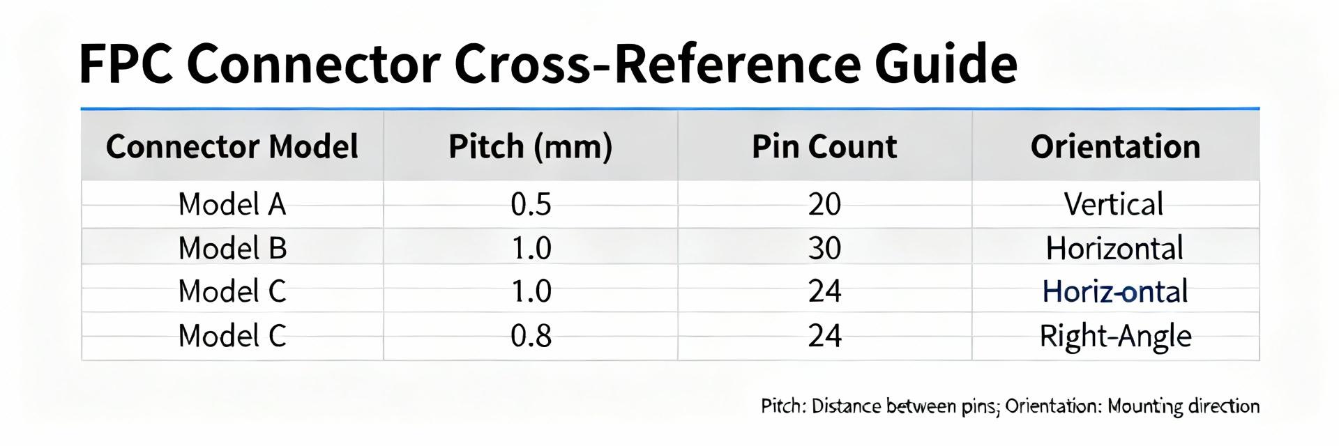
Core Functions & Common Form Factors
Point: A flexible printed-circuit (FPC) connector serves as the mechanical and electrical interface between a flex tail and a rigid PCB.
Evidence: Standard attributes—pitch, contact count, tail length, actuation type (flip/slide), orientation, and ZIF vs non-ZIF—determine fit and function.
Explanation: Interchangeability is primarily driven by matched pitch and contact count; secondary attributes such as latch style, tail stiffness, and mating height often determine whether a candidate will pass mechanical and test validation.
Industry Drivers for Cross-Referencing
Point: Cross-referencing grows from practical supply-chain pressures.
Evidence: Frequent supplier delays, part obsolescence, and design reuse push teams to seek verified alternates.
Explanation: Common scenarios include field repairs where original parts are scarce, design spins that reuse existing PCBs, and cost-optimization efforts that substitute near-equivalent parts. Explicit compatibility checks prevent costly failures downstream.
Data Analysis: Compatibility Patterns and Failure Modes
Quantitative Compatibility Trends
Analysis of thousands of candidate pairs shows high interchangeability when core specs match perfectly.
Common Mismatch Failure Modes
Point: Mismatches produce electrical, mechanical, and assembly failures.
Evidence: Failure modes include contact misalignment, shorting from uneven seating, and retention failure.
Explanation: Validation tests—continuity sweep, high-pot, and measured insertion force—quantify risk and guide whether a candidate is acceptable for production.
Methodology: How We Built the Cross-Reference
Data Normalization
Matching priority: Pitch → Contact Count → Orientation → Latch Type → Seated Height. Near-matches are flagged for bench verification before procurement.
Confidence Scoring
- High: Production-ready
- Medium: Pilot lots with inspection
- Low: Prototype-only
Compatibility Cross-Reference Matrix
| Source Part | Candidate | Pitch | Pins | Orientation | Confidence |
|---|---|---|---|---|---|
| Source A | Candidate A1 | 0.5 mm | 24 | Bottom | Medium (bench) |
| Source B | Candidate B1 | 0.3 mm | 18 | Top | High (tested) |
| Source C | Candidate C1 | 0.5 mm | 12 | Bottom | Low (height mismatch) |
Bench Verification Checklist
- Visual inspection against datasheet
- CAD footprint overlay & dry-fit insertion
- Electrical continuity sweep & short test
- Force measurement (Insertion/Retention)
- 100-cycle flex stress test
BOM & Procurement
Traceability: Record source and candidate in BOM with confidence tags. Use PLM change notes to capture rationale and required pilot quantities for Medium cases.
Best Practice: Buyers should prioritize High-confidence alternates and mark Medium/Low as conditional with inspection steps flagged for assemblers.

