
Comprehensive analysis of failure modes, MTBF fundamentals, and reliability optimization strategies.
Field reliability programs typically report failure rates spanning parts-per-million-per-year to single-digit FIT levels depending on stress — translating to MTBFs from 106 to 109 device-hours. This report focuses on 06035C472K4Z2A MLCC behavior and practical steps designers can use to quantify and improve component reliability.
Background: Part Overview & Reliability Context
Component Snapshot & Typical Use Cases
The 06035C472K4Z2A is a 0603-package multilayer ceramic capacitor (MLCC) with a nominal capacitance of 4.7 nF (4700 pF), rated at 50 V with an X7R dielectric. It is widely utilized in:
- Power-decoupling & high-frequency filtering.
- Automotive & industrial power electronics.
- High-reliability consumer subsystems.
Reliability Baseline & Industry Framing
Industry metrics leverage FIT (Failures In Time) and MTBF. For constant-rate assumptions:
Example: 100 FIT corresponds to an MTBF of ≈ 107 hours. X7R dielectrics require careful balancing of capacitance vs. aging effects.
Key Failure Modes for 06035C472K4Z2A
Mechanical & Assembly-Induced
Leading causes of field loss in vibration-stressed assemblies:
- Body Cracking: Often due to board flexure.
- Termination Fracture: Solder-joint fatigue.
- Pick-and-Place Stress: Aggressive pressure during assembly.
Electrical & Environmental
Degradation mechanisms affecting long-term stability:
- DC-Bias Drop: Capacitance reduction under voltage.
- Dielectric Aging: Permittivity reduction over time.
- Leakage/Shorts: Moisture or contamination-induced.
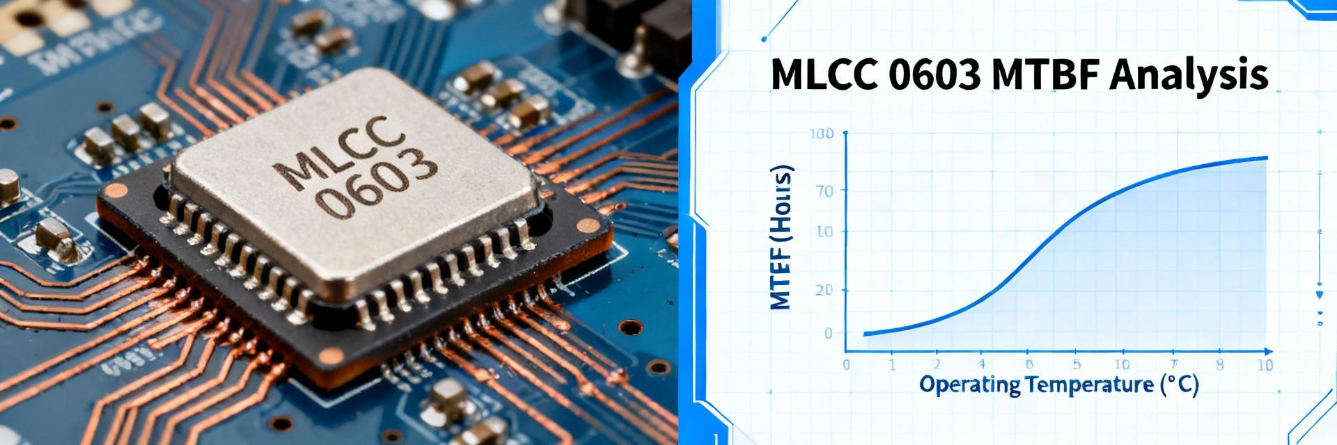
MTBF Fundamentals & Metrics
Visualizing Reliability (FIT vs. MTBF)
Worked Example: For zero failures in a sample size over total device hours, use a 95% confidence bound:
λ_upper ≈ 3 / total_device_hours
Accelerated Testing & Screening Methods
| Test Category | Parameters (Typical) | Failure Target |
|---|---|---|
| Temperature-Humidity Bias (THB) | 85°C / 85% RH / Rated Voltage | Moisture-induced leakage / Shorts |
| High-Temperature Bias (HTB) | 125°C / 2x Rated Voltage | Dielectric conduction / Aging |
| Thermal Shock | -55°C to +125°C (1000 Cycles) | Solder/Termination fatigue |
| Board Flex | 2mm - 5mm deflection | Mechanical cracking |
Case Studies & Field Failure Examples
Board-Level Flex Issues
"Intermittent regulator dropout near board edges."
Root cause identified as edge cracks via X-ray. Mitigation involved moving the MLCC 5mm away from the board edge and optimizing reflow profiles.
DC-Bias induced Margin Loss
"Increased ripple and instability under high load."
Capacitance reduction under DC bias was exceeding safety margins. Fixed by switching to a larger nominal capacitance and applying 50% voltage derating.
Design & Quality Checklist
Selection & Layout
- ✓ Apply voltage derating (Ideally 50% of rated voltage).
- ✓ Maintain distance from board edges, screw holes, and cutouts.
- ✓ Use optimized pad geometries to reduce stress concentration.
Production & Monitoring
- ✓ Implement lot-level incoming inspection and traceability.
- ✓ Conduct accelerated burn-in for high-stress applications.
- ✓ Establish feedback loops from field returns to qualification labs.
Summary
- Mechanical cracking, DC-bias degradation, and moisture-induced shorts are primary failure modes impacting MLCC function; targeting layout, termination design, and assembly controls yields highest impact on field reliability.
- Calculate MTBF from observed failures and device-hours (MTBF = 1/λ); when zero failures occur use statistical upper bounds to report conservative FIT estimates and confidence intervals.
- Use a focused accelerated test matrix (THB, HTB, thermal cycling, board flex) and clear acceleration assumptions to convert lab hours to field-equivalent life and drive derating and design changes.

