
Introduction: Lab and field measurements show that 0603 MLCCs with X7R dielectric at 1000pF and 50V commonly exhibit measurable DC-bias capacitance loss and temperature-dependent drift. Typical observed DC-bias loss ranges from ≈10–40% at 50V depending on dielectric thickness and pellet geometry. This piece gives a practical, testable breakdown of specs, reliability data, failure modes and selection/inspection guidance so you can choose and validate parts for production; reference part example: 06035C102K4Z2A appears in vendor catalogs and can be tested to the procedures below.
Introduction (continued): Data-driven selection requires reading DC-bias curves, life-test tables and physical tolerances. Measured ESR/ESL trends on 0603 parts show relatively higher series impedance vs. larger packages, so layout and expected in-circuit impedance must be verified under bias and temperature. Use the stepwise recipes below to reduce field surprises.
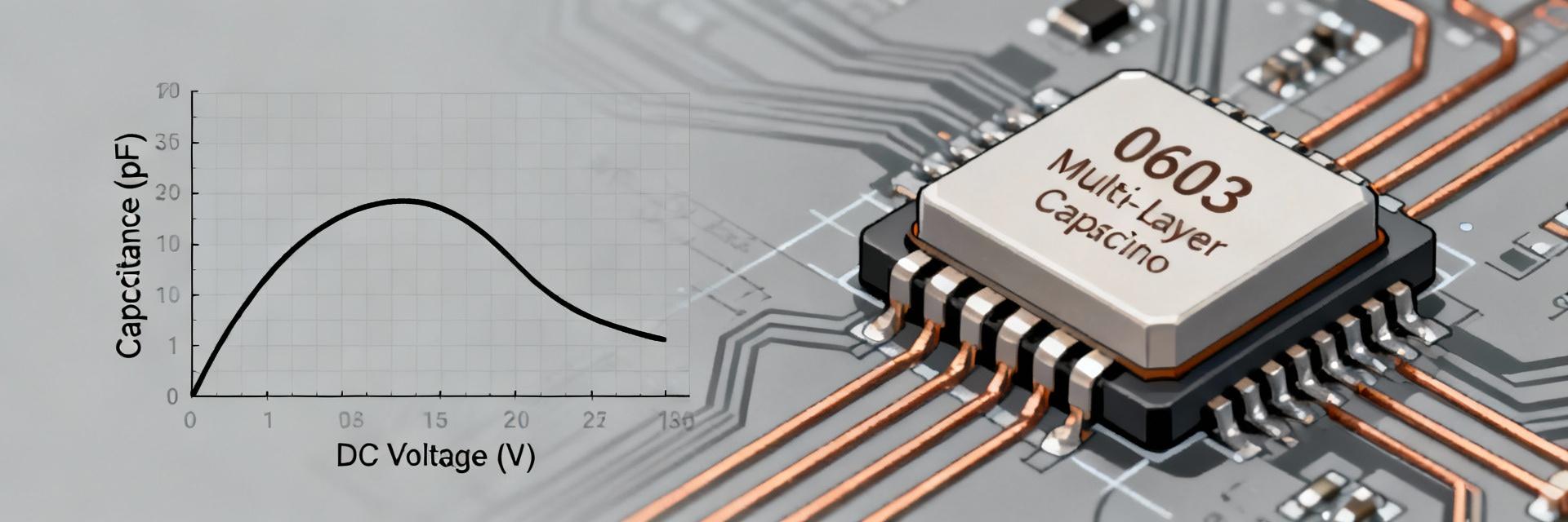
Typical Capacitance Retained vs. DC Bias (50V)
*Typical X7R 0603 1000pF degradation profile
Background: MLCC 0603 1000pF X7R 50V — baseline specs and common uses
Point: The 0603 MLCC (EIA 0603 / 1608 metric) nominally offers 1000pF with common tolerances ±10% or ±20% and an X7R temperature characteristic rated −55°C to +125°C; rated DC voltage is 50V. Evidence: Typical sheet data lists capacitance, tolerance and temp class; ESL/ESR rise as package shrinks. Explanation: Because 0603 geometry limits electrode area and dielectric thickness control, X7R 1000pF parts trade capacitance stability for size—expect higher ESR and modest ESL compared with 0805 or larger parts, and pay attention to termination and mounting recommendations to avoid mechanical stress.
Physical & Electrical Baseline
- EIA 0603 (1.6mm x 0.8mm) nominal dimensions
- 1000pF (1nF) capacitance value
- X7R Temperature Coefficient (±15% ΔC)
- 50V DC Rated Working Voltage
- Controlled ESR/ESL for High-Frequency decoupling
Typical Applications
- Power-rail decoupling & EMI filtering
- Analog signal bypass and noise suppression
- Timing networks (where ±15% drift is acceptable)
- In-circuit impedance matching
How to read datasheets for MLCC 0603 1000pF X7R 50V
Point: Datasheets vary in which curves and test conditions they publish; read for nominal capacitance, tolerance, DC-bias curve, temperature characteristic, rated voltage, tanδ and insulation resistance. Evidence: Manufacturers sometimes present DC-bias at different frequencies and voltages; life-test durations differ. Explanation: Verify which frequency the DC-bias curve uses, and ensure life-test conditions (temperature, voltage, duration) match your application; require explicit solder profile and mechanical robustness data.
| Key Parameter | Requirement / Check | Red Flag / Warning |
|---|---|---|
| DC-Bias Curve | Verified at 1kHz or 1MHz as per standard | Curve missing or shown at unrealistic bias |
| Life Test | 1000-2000 hours at 125°C, 2x Rated Voltage | Short durations ( |
| Mechanical | Flex/Bending test data (typically 2-3mm) | Absent mechanical crack/robustness data |
| Dissipation (tanδ) | Standard limits (usually | Inconsistent reporting frequencies |
Reliability data & expected electrical behavior (include DC bias)
Point: DC-bias and temperature produce measurable capacitance shifts; a 1000pF X7R in 0603 can lose ~10–40% capacitance at 50V. Evidence: LCR voltage-sweep measurements at relevant frequencies reveal normalized C vs. V curves; temperature chamber sweeps show X7R’s temperature dependence. Explanation: Plot normalized capacitance vs. bias and temperature to quantify in-circuit effective capacitance and determine whether derating or alternate dielectrics are needed.
Standard Reliability Tests
- HTL (High Temp Life): Pre/Post Cap check
- 85/85 Humidity: Moisture resistance verification
- Thermal Shock: -55°C to +125°C cycling
- AEC-Q200: If automotive scope is required
DC-Bias & Temp Checklist
- Measure 0 → Rated Voltage in steps
- Check Tanδ shift alongside Capacitance
- Verify behavior at -40°C and +125°C
- Compare measured results with factory plots
Failure modes, root causes and mitigation (include derating)
Mechanical failure & assembly-related causes
Dielectric aging, shorting and electrical degradation
Application examples & bench test recipes
Point: Validate in-circuit performance with focused bench tests: C vs. DC bias, thermal sweep, and post-reflow checks. Evidence: Measured impedance under bias shows reduced effective capacitance and shifted resonances; documentation of test conditions prevents misinterpretation. Explanation: Use the recipes below to create reproducible supplier and incoming inspection protocols.
Validation Recipe
- LCR meter at target frequency (e.g., 1kHz)
- Sweep DC bias 0V to 50V
- Thermal chamber sweep -40°C to +125°C
- Check Insulation Resistance (IR) at 50V
- Record Pre/Post reflow Cap values
Example Outcomes
- Power Rail: Expect reduced effective C under load; ensure bulk capacitance remains sufficient.
- Timing Bypass: If stability is critical, compensate for bias drop or switch to NP0/C0G.
Selection checklist and procurement / incoming inspection controls
Pre-purchase Spec Checklist
- Confirmed 0603 Footprint
- X7R Dielectric (-55 to +125°C)
- 50V DC Rating (Min)
- Published DC-Bias Curves
- RoHS/REACH Declaration
- AEC-Q200 (For Auto/Industrial)
Incoming Inspection Plan
- Visual Inspection for Cracks
- Random LCR Capacitance Sweep
- DC-Bias Spot Check at 25V/50V
- Solderability Sample Test
- Lot-Code Traceability Verification

