
This report uses measured-oriented guidance: what to verify in a datasheet, behavior vs. environment, and bench validation steps.
Background: Understanding 06035A220KAT and its Market Position
Point: Decode the marking and place the part in the product stack. Evidence: Typical MLCC part codes embed package, capacitance code, tolerance, voltage, and series information. Explanation: Designers should treat the printed code as shorthand—always cross-check the datasheet for exact mapping because vendor series suffixes vary.
Part-code breakdown and physical footprint
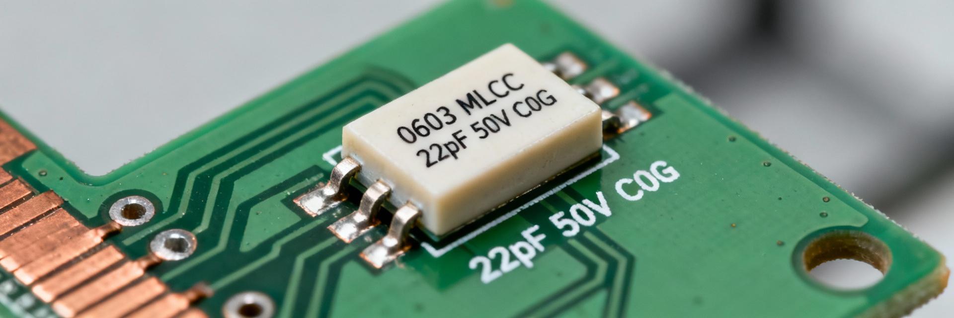
- 0603: Package size (imperial 0603, nominal footprint ≈ 0.06" × 0.03");
- 220: Capacitance code representing 22 pF;
- K: Tolerance indicator (commonly ±10%);
- 50 V: Rated DC working voltage (explicit on datasheet);
- C0G: Dielectric class (stability and loss characteristics).
Dielectric overview: C0G (NP0) properties
C0G provides the most stable MLCC dielectric for precision uses, exhibiting approximate 0 ±30 ppm/°C temperature coefficient and negligible aging.
Detailed Electrical Specifications & Performance Data
A focused spec table consolidates the key capacitor specs designers verify before selection to reduce errors and support procurement comparisons.
| Parameter | Typical / Target Value |
|---|---|
| Capacitance | 22 pF |
| Tolerance | ±10% (K) — verify marking |
| Rated Voltage | 50 VDC |
| Dielectric | C0G (NP0) |
| Dissipation Factor (DF) | |
| Insulation Resistance | High — datasheet lists µA or GΩ spec |
| SRF (Self-Resonant Frequency) | High hundreds of MHz to low GHz range |
* SEO Note: Include "capacitor specs" in procurement datasheets.
Measurement & Validation: Bench Testing Procedures
Recommended Setup
- Tools: Precision LCR meter, impedance analyzer.
- Conditions: Small-signal AC at 1 kHz and target RF frequencies.
- Calibration: Open/short/load compensation is mandatory.
Typical Applications and Use-Case Selection
Best-Fit Applications
- Precision timing networks
- Oscillator tuning (low drift)
- RF matching and filtering
- ADC front-ends / sample-and-hold
Design Reliability
Apply conservative design margins. Use moderate voltage derating and verify reflow profile compatibility to avoid mechanical stress failures.
Purchasing, Equivalents, and Implementation
Final Implementation Checklist
Summary
The 06035A220KAT is a 22 pF, 50 V, C0G MLCC in 0603 packaging whose capacitor specs favor stable, low-loss performance for timing, RF matching and precision analog work. Designers should validate SRF, DF and leakage, and run bench verification before volume production.
- Verify core specs: 22 pF, 50 V, C0G dielectric.
- Measure using calibrated LCR meters before production.
- Validate SRF and dissipation factors under representative conditions.

