06035A102GAT MLCC: C0G 0603 100pF 50V Data Brief & Insights
2026-01-29 20:57:17
Product Overview
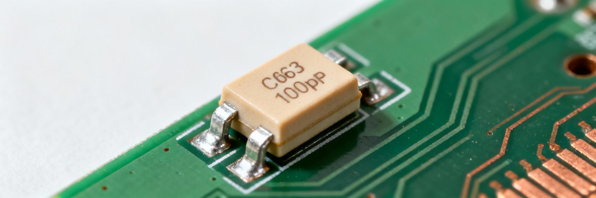
The 06035A102GAT is a precision 0603 MLCC tuned for stability and repeatability in compact designs. Typical commercial offerings in this family present tight tolerances and 50 V ratings for margin in analog and RF use.
Capacitance: 100 pF
Tolerance: ±1%, ±5%, ±10% (select per design accuracy)
C0G dielectric guarantees near-zero change over temperature; ESR and ESL are dominated by package and layout. For 0603 100pF parts, ESR is typically single-digit milliohms to tens of milliohms at low frequency.
C0G Temperature Drift (±30 ppm/°C)Extremely Low
Standard High-K Dielectric DriftSignificant
Why C0G (NP0) Dielectric Matters for 100pF 50V Applications
Temperature and Frequency Stability
C0G provides essentially 0 ppm/°C behavior within rated ranges, unlike X7R or Y5V. Evidence: C0G is specified to ±30 ppm/°C or better, while high-K classes can shift by several percent per 10–40°C. In timing circuits and precision filters, C0G 0603 100pF stability preserves center frequency and phase margin.
Bias Dependence and Ageing
NP0/C0G exhibits negligible DC bias and ageing compared with high‑K dielectrics. High-K MLCCs can lose significant capacitance under typical DC bias; NP0 parts show
Mechanical Robustness & Assembly Considerations
Proper land pattern and paste aperture reduce tombstoning and solder fatigue for 0603 MLCCs. 0603 MLCC cracking stems from board flex, tight corner fillets, and excessive assembly stress.
Land Pattern Element
Typical Dimension (mm)
Pad length
0.6–0.7
Pad width
0.5–0.6
Pad spacing (board)
0.8–0.9
Stencil aperture
60–80% per pad
Recommended Test Procedures
Essential lab tests include C vs frequency (100 kHz–1 GHz), insulation resistance, DC bias capacitance check at relevant voltages, temperature cycling, and humidity soak. Capture curves for inclusion in the data brief to ensure precision.
Screening & Reliability
Accelerated stress tests reveal latent defects. Use temperature-humidity-bias (THB), thermal shock, and life testing to monitor degradation modes such as insulation decline or microcracking. Adopt an AQL-based sampling plan.
Use Cases & Design Examples
RF & Timing
Crystal load capacitors and RF matching where linearity preserves filter Q. Match capacitance to manufacturer recommendations and place symmetrically.
Analog Front-End
Precision RC filters and ADC front-end coupling. Place the MLCC close to the active device to minimize loop area and stray inductance.
Procurement & Lifecycle Checklist
✓
Verify package (0603) and dielectric (C0G/NP0).
✓
Confirm 50V rating and RoHS compliance.
✓
Record datasheet revision and internal footprint ID.
Maintain safety stock and vet at least two approved form-fit families for cross-reference. Order production lots to cover several builds and keep lot traceability for long-term reliability.
Frequently Asked Questions
What makes a C0G MLCC like 06035A102GAT preferable for precision timing?
+
C0G offers near-zero temperature coefficient and negligible bias dependence, keeping capacitance stable across temperature and applied voltage. For timing circuits where ppm-level drift changes frequency, a 100pF C0G in 0603 ensures predictable RC time constants and reduces calibration frequency.
How should engineers verify soldering and footprint for 0603 MLCCs?
+
Validate footprint dimensions against the chosen part’s recommended land pattern, use a 60–80% stencil aperture per pad, and follow a controlled reflow profile with a moderate ramp and 60–90 second peak time. Include AOI and selective X‑ray checks during initial runs to confirm joint quality.
What tests are essential to qualify a lot of MLCCs for production?
+
Key tests include capacitance vs frequency, capacitance vs DC bias, insulation resistance, temperature cycling, humidity soak, and accelerated THB. Define pass/fail thresholds in the qualification plan and sample across multiple reels or lots for statistical confidence.