
MLCC Overview: Form Factor & Coding
Size, Package Code, and Capacitance Decoding
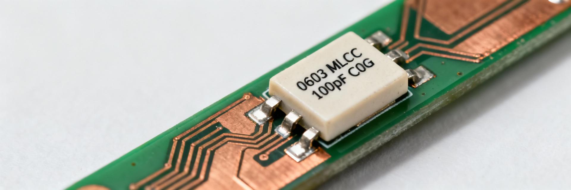
The "0603" footprint refers to an imperial 0.06" × 0.03" surface-mount device (SMD) size. The marking "101" decodes as 100 pF (the digits 10 followed by 1 zero in picofarad notation). PCB land patterns should strictly follow vendor-recommended pads to minimize solder fillet variability; while smaller sizes generally yield lower Equivalent Series Resistance (ESR) and Equivalent Series Inductance (ESL), they require tighter placement precision to reduce parasitic effects.
Dielectric Families and C0G/NP0 Implications
Dielectric choice fundamentally governs stability and energy loss. C0G (also known as NP0) dielectrics exhibit a near-zero temperature coefficient and an extremely low dissipation factor compared to the X7R or Y5V families. It is best to choose C0G for precision timing and filtering applications where capacitance must remain constant; reserve X7R for higher bulk decoupling where larger capacitance per unit volume is prioritized over ppm-level stability.
Datasheet Breakdown: Electrical Specs for 06035A101KAT
Key Electrical Specifications
The following table distills the most critical parameters for rapid design verification. These values are presented alongside standard test conditions to ensure accurate interpretation regarding bias or frequency effects.
| Specification | Typical Value | Visualization & Notes |
|---|---|---|
| Nominal Capacitance | 100 pF | Code: 101 Measured at 25°C |
| Tolerance | ±10% (K) | Standard Industry Code |
| Rated Voltage | 50 V DC | Typical rating; verify bias derating |
| Dielectric | C0G / NP0 | Ultra-stable Temperature Coefficient |
| Dissipation Factor | Measured at 1 MHz | |
| ESL / ESR | Ultra-Low | Frequency-dependent; refer to vendor plots |
Test Conditions & Measurement Notes
Measurement conditions significantly influence reported values. Datasheets typically specify frequency (1 MHz for low values, 1 kHz for high values), temperature, and applied AC/VDC test levels. Designers should monitor for capacitance reduction under DC bias and at elevated temperatures. Always reference the specific test frequency when comparing components and follow vendor derating curves when operating in high-bias environments.
Environmental & Reliability Specs: Temperature, Life, and Derating
Temperature Range and Stability Implications
The operating range influences both instantaneous capacitance and long-term lifetime. C0G components typically offer wide operating ranges (e.g., -55°C to +125°C) with negligible drift. You can expect minimal capacitance change across the entire thermal profile; use the dielectric stability table to predict performance at extreme temperatures and to accurately model filter Quality (Q) factors and timing precision.
Reliability Metrics to Monitor
Standard datasheets list life tests and mechanical constraints that correlate to board-level reliability. Key metrics to evaluate include the Moisture Sensitivity Level (MSL), mechanical shock and vibration ratings, life test hours (e.g., 1000 or 2000 hours at rated voltage/temp), and failure-rate data. Use these metrics to determine requirements for conformal coating, component placement relative to thermal sources, and sample lot testing for critical missions.
Applications, Equivalent Parts & Selection Tips
Typical Applications for 100 pF C0G 0603 MLCC
The 06035A101KAT excels in environments where stability and low loss are paramount. Common applications include:
- RF matching networks and impedance tuning.
- Crystal oscillator load capacitors.
- Precision analog filters and timing circuits.
- High-speed ADC front-end decoupling.
A 50V rating provides significant headroom for bias in mixed-signal circuits, ensuring that ppm-level stability translates directly to frequency accuracy in the final product.
Finding Equivalents: A Comparison Guide
Equivalence involves more than just matching capacitance and size. When sourcing alternatives, you must match the dielectric type (C0G/NP0), tolerance (±10%), voltage rating (50V+), and ESR/ESL profiles. Prefer manufacturers that provide published frequency sweep data to ensure seamless interchangeability in RF or timing-sensitive applications.
Practical Checklist: Sourcing, PCB Verification & Test Procedures
Pre-Sourcing Checklist
- ✅ Confirm exact part number and package suffix.
- ✅ Verify tolerance (K = ±10%) and dielectric (A = C0G).
- ✅ Check RoHS/REACH compliance status.
- ✅ Review reel size for automated assembly compatibility.
- ✅ Confirm lead times and shelf-life requirements.
PCB Verification Steps
- 🔍 Visual inspection for "tombstoning" or alignment.
- 🔍 Solder fillet assessment via AOI (Automated Optical Inspection).
- 🔍 Board-level impedance sweep for high-frequency paths.
- 🔍 In-circuit capacitance measurement at target frequencies.
- 🔍 Verification of reflow profile against datasheet thermal limits.
Summary
- 06035A101KAT identifies a 100 pF value in an 0603 package; always verify the "101" decode and the "K" tolerance for precise circuit performance.
- C0G/NP0 Dielectric ensures superior temperature stability and ultra-low dissipation, making it ideal for RF, timing, and precision filtering.
- Critical Verification: Evaluate rated voltage, DC bias curves, and mechanical reliability before procurement to mitigate assembly risks such as dielectric cracking.
FAQ
How does the capacitance code decode for this MLCC?
The three-digit code represents the nominal value in picofarads (pF). For "101", the first two digits (10) are the significant figures, and the third digit (1) is the multiplier (10^1). Thus, 10 × 10 = 100 pF. Always confirm the tolerance code following this value to ensure it meets your design's precision requirements.
What derating should be applied relative to rated voltage?
DC bias can reduce the effective capacitance in some MLCC families. While C0G dielectrics are significantly more stable than X7R under bias, it is best practice to review the manufacturer's Voltage vs. Capacitance curves. If specific data is unavailable, maintain a safety margin of at least 20% below the rated 50V for long-term reliability.
What in-circuit tests confirm MLCC integrity after assembly?
Integrity is confirmed through a combination of visual and electrical checks. Use AOI to detect physical displacement or tombstoning, and perform an in-circuit capacitance test or impedance sweep. These tests help identify cracked dielectrics—a common failure mode caused by excessive board flexure or aggressive thermal reflow profiles.

