30-Position
0.8mm Pitch
SMT Right-Angle
Key Quick Facts
Aggregated listings show a consistent part-class profile: 30-position, 0.8mm pitch board-to-board mezzanine header. Typical ratings: 0.5 A/contact, ≤40 mΩ resistance, up to 105°C, MSL 1.
Design Purpose
This guide provides a compact, data-backed checklist for PCB designers and buyers to lock down critical mechanical, electrical, and assembly parameters and avoid footprint rework.
Connector Overview & Identification
Part Number Designation
The designation denotes a low-profile board-to-board / mezzanine SMT header intended for compact module stacking. For layout, this requires fine-pitch pad geometry, tight courtyard clearances, and specific mechanical alignment features.
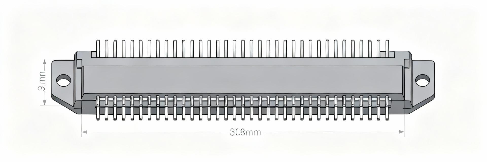
Physical Attributes Checklist
Extract these items before creating the footprint: pitch (0.8mm), pin count (30), row spacing, mated/unmated heights, shroud features, and tape-&-reel details for automated assembly.
Data Analysis: Electrical & Mechanical Specs
| Parameter |
Typical Value |
Maximum |
Design Note |
| Current per contact |
~0.5 A |
— |
Size traces per worst-case derating |
| Contact resistance |
≤40 mΩ |
— |
Impacts low-voltage drop designs |
| Mating cycles |
~30 |
— |
Choose finish per lifecycle |
Trace Width Recommendation (IPC-2152 Based)
External (1oz):
8 – 12 mil
*Based on 0.5A current rating. Apply a +25% derating factor for safety in high ambient conditions.
Thermal & Environmental Limits
Capture maximum operating temperature, peak reflow profile, and MSL rating (MSL 1). Validate reflow profiles with the connector’s recommended peak and soak times to ensure structural integrity.
PCB Spec Checklist
Follow the datasheet land pattern exactly. For 0.8mm pitch SMT headers, start with a 60–80% paste aperture of pad area to prevent bridging while ensuring wetting.
Compatibility & Assembly Guidance
-
✔
Application Scenarios: Ideal for board stacking and mezzanine modules where low-profile alignment precision is paramount.
-
✔
Interoperability: Confirm exact mating part number and finish (tin vs gold) as it affects signal integrity and lifecycle.
-
✔
Assembly Rules: Use clear placement fiducials and confirm board warpage limits to avoid multi-row placement failures.
Design-to-Procurement Action Checklist
1
Pre-Layout Verification
Obtain latest 3D STEP file, create schematic symbol/footprint, and run DRC/DFM checks for 0.8mm pitch before production.
2
Procurement & QA
Check lot traceability and MSL status. Perform incoming visual inspection and a sample solderability test on first articles.
Summary
Lock down mechanical and electrical limits, follow datasheet land patterns, and validate with sample assembly. Final Action: Verify every numeric value against the official datasheet before volume production.
- Confirm mechanical drawing revision and STEP file for pitch and pin count.
- Extract electrical limits and calculate trace widths with safety margins.
- Use 60–80% paste aperture and validate with first-article PCBA inspection.
Frequently Asked Questions
How should designers verify the 0533093070 connector pad geometry?
▼
Obtain the official land pattern and 3D STEP from the datasheet package and cross-check pad dimensions, courtyard, and mechanical keepouts in your CAD. Create a dedicated component with the exact revision and run DRC/DFM checks against board stack-up and stencil aperture.
What trace width should be used for a 0.5 A rating on the 0533093070 connector?
▼
Use an IPC-2152 calculator: for 0.5 A on an external 1 oz copper trace, target roughly 8–12 mil depending on allowable temperature rise; increase width for internal layers and apply a safety derating of ~25%.
Which acceptance tests should procurement run on samples?
▼
Perform lot and packaging inspection, dimensional checks, a solderability check, and one PCBA first-article with mechanical mating tests. Include basic electrical continuity and a small sample of mating-cycle testing.