
Struggling to identify the exact length, pitch, or pin count of a flat flex cable before ordering a replacement or designing a connector? This concise guide explains step-by-step how to measure an FFC correctly to avoid fitment errors and signal problems.
01 Background & Key Terms
What is an FFC cable?
Point: An FFC cable is a flat flexible cable used to connect PCBs and modules in compact assemblies. Evidence: Common uses include LCD panels, camera modules, and sensors where routing space is limited. Explanation: Called both "FFC cable" and "flat flex" in field notes, these cables have parallel conductors laminated between dielectric films; accurate specs matter because small errors in pitch or exposed contact length can prevent proper mating and cause intermittent signals.
Key specifications you’ll see on drawings or part codes
Point: Typical spec fields include overall length, exposed contact length, pitch, conductor count/pins, termination side, and orientation. Evidence: Drawings usually list mm values and tolerances; converters use inch equivalence. Explanation: Keep a short glossary: overall length (end-to-end), exposed contact length (pad beyond insulator), pitch (center-to-center conductor spacing in mm), conductor count (pins), and termination side (which face the pads are on). Always note units and tolerance ± values.
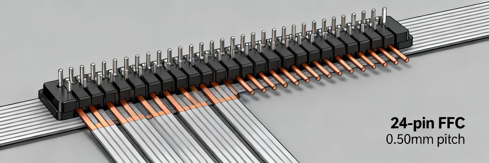
02 050R24-102B: Typical Dimension Summary
A 050R24-102B-style cable typically appears as a 24-pin FFC with 0.50 mm pitch and an overall length near 101.6 mm (4.000").
Tools & Prep: What You Need
Essential Tools
- Digital Calipers (0.01 mm)
- Stainless Steel Ruler
- Magnifier or Microscope
Best Practices
- ESD-Safe Mat & Strap
- Non-Reflective Surface
- Macro Camera for Docs
03 Measurement Workflow
Step 1: Measuring Length
Lay the FFC flat with no twists. Measure from the outer-most edge of one end to the other using calipers. Record in mm and repeat twice to ensure precision.
Step 2: Exposed Contact Length
Measure the conductive pad distance beyond the flexible backing. Align caliper jaws to the pad start and measure to the tip. Note if pads are masked or tinned.
Step 3: Calculating Pitch (N-Span Method)
To reduce error, measure across N conductors and divide by (N-1).
Quick Action Checklist
- ✔ Overall length: Recorded in mm with repeat measurement.
- ✔ Exposed contact: Length and surface finish identified.
- ✔ Pitch & Pins: Verified via N-span calculation (e.g., 24 pins @ 0.50mm).
- ✔ Termination: Side confirmed (Top vs Bottom) with macro photo.
Frequently Asked Questions
How do I confirm the pitch on an unknown FFC cable? +
What measurements should I send when ordering a replacement? +
Can I rely on a printed part code without measuring? +
Summary
Accurate FFC length, pitch, and pin-count measurements prevent costly fit and function failures—especially for parts like the 050R24-102B where small pitch (0.50 mm) and a 24-pin count are standard.
- Record overall length in mm; note total length vs exposed contact length.
- Measure pitch using N-span (length ÷ (N-1)) for best accuracy.
- Count pins visually and confirm termination side (Top/Bottom).

