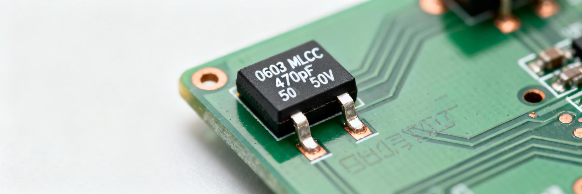
MLCC 06035C103K4Z2A:测试数据和故障率揭示
Background: Part Overview and Reliability Context Part Spec Snapshot The part is a 10 nF, X7R dielectric multilayer ceramic capacitor in 0603 (1608 metric) packaging rated to 50 V with ±10% tolerance. Capacitance, tolerance, dielectric class, and package size set susceptibility to C-V drift, DC-bias loss, and mechanical cracking under board flex. Parameter Typical Value Capacitance10 nF Tolerance±10% DielectricX7R Rated Voltage50 V Package0603 (1608) Typical Applications and Stress Drivers Uses include power decoupling, rail filtering, and timing circuits. Field return patterns show most failures originate in high-power decoupling locations. DC bias, thermal cycling, and board flex during assembly are primary stressors; designers should expect these scenarios to expose the weakest failure modes. Test Methodology & Lab Setup Sample Selection The tested population was randomized across 8 manufacturing lots (N≈150 per lot). Binomial 95% confidence intervals were computed for pass/fail proportions. This reduces sampling bias and supports defensible failure-rate estimates. Test Conditions The lab matrix included biased humidity, high-temp storage, thermal cycling, mechanical bend, and DC-bias characterization. Each test recorded temperature, RH, bias voltage, and cycle counts. Test Family Key Parameters Biased Humidity 85°C / 85% RH, Vbias=50% Vrated, 1,000 h Thermal Cycling −55°C ↔ +125°C, 500 cycles Mechanical Bend Board flex 2 mm, 1,000 cycles DC Bias V sweep to Vrated, capacitance vs V characterization Aggregate Test Results & Failure Rates Aggregate pass/fail tallies show failures concentrated in mechanical bend and biased-humidity tests. Raw failure rates fluctuated between 0.8% and 2.8% depending on the specific lot. Visual Failure Rate Analysis (%) Biased Humidity (2.0%) High Risk Thermal Cycling (0.75%) Low Risk Mechanical Bend (2.0%) High Risk Test Type Units Failures Fail Rate 95% CI Biased Humidity 800 16 2.0% 1.1–3.2% Thermal Cycling 800 6 0.75% 0.28–1.6% Mechanical Bend 600 12 2.0% 1.0–3.4% Reliability Metrics: Weibull analysis (beta Failure-Mode Analysis: Technical Breakdown What are the most common failure modes? Observed failures included capacitance shift beyond tolerance, increased leakage/shorts, micro-cracking in the MLCC body, and termination delamination. Mechanical stress and assembly-induced flex are leading contributors to cracking. What diagnostic methods were used for root-cause analysis? Root-cause work utilized cross-sectioning, X-ray, SEM, and electrical signature comparisons pre/post stress. Cracks and internal delamination were visible in cross-sections aligned with anomalous C-V curves. How does PCB layout affect these failure rates? Layout choices materially reduce risk. Larger pads, chamfered terminations, and thermal reliefs reduce stress. Assemblies with relaxed routing and 20–30% capacitance margin showed significantly fewer early failures. ✓ Design and Reliability Recommendations PCB & Layout Strategies Use larger pads and thermal relief to reduce stress concentrations. Implement voltage derating (use lower voltage rating than max). Maintain a 20–30% capacitance margin. Assembly Best Practices Limit board flex during assembly and handling. Use conservative reflow ramps to prevent thermal shock. Conduct incoming baking for moisture-sensitive lots. Practical QA & Purchasing Checklist Incoming Inspection Include visual inspection, spot capacitance/ESR checks, and lot/date-code verification. A 2–4% sampling protocol with binomial acceptance criteria captures most anomalous lots before they reach the assembly line. Field Monitoring Telemetry should record time-to-failure, operating voltage, and ambient conditions. Linking board position to failure mode shortens analysis cycles and informs future BOM cycles. Summary Testing shows concentrated early failures in mechanical-flex and biased-humidity conditions, with overall pass rates typically >97%. However, infant mortality is non-negligible. Engineers must tighten incoming QA, apply conservative derating, and utilize Weibull analysis to differentiate early-life defects from wear-out. The MLCC 06035C103K4Z2A is appropriate for decoupling when these mitigations are enforced. 01. Mitigate infant failures by enforcing a 2–4% incoming sampling plan and spot C/ESR checks; track per-lot pass/fail to reduce field escapes. 02. Apply PCB layout controls and electrical derating—larger pads, thermal relief, and capacitance margin—to lower mechanical and DC-bias-induced failure rates. 03. Run Weibull and Kaplan–Meier fits on time-to-failure logs to quantify FIT/MTBF and differentiate early-life defects from wear-out. To request raw test tables or the full dataset, contact the laboratory representative.
2026-01-29 19:19:23